CVA-7 CV Analyzer
Product Info
CVA-7 is a free (and open source) rack extension for Reason, the music DAW produced by Reason Studios. This 2U utility lets you analyze a CV signal in various ways. It can also act as a CV Spider Splitter on steroids (converts the input signal into an inverse, unipolar or bipolar signal).Main features
- Analyze and interpret an incoming CV signal with graph, keyboard and numeric displays
- Freeze time for detailed analysis
- Easily convert an incoming signal into its inverse, unipolar or bipolar version (up to 4 outputs)
- Use AUX OUT CVs for controlling other devices in a creative way
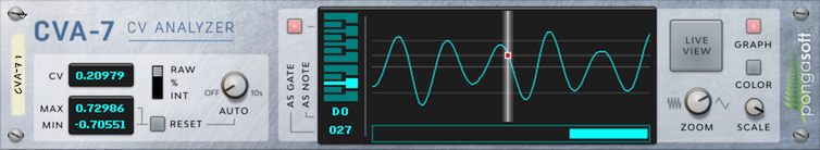
Front
Folded Front

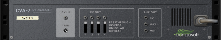
Back
Features
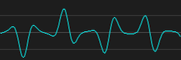
CV Analyzer (graph)
- The main LCD screen displays the CV signal live as a graph
- Zoom in and out to see more details (from real time to 30s)
- Freeze the display for detailed analysis by clicking directly in the scrollbar or on the screen itself
- Use the toggle to resume or stop live view
- Use the toggle to turn the screen on or off
- Use the COLOR button to switch between 5 different colors
CV Analyzer (keyboard)
- Interpret the incoming CV signal as a note or a gate
- Use the toggle to turn the keyboard on or off
CV Analyzer (numeric)
- Display the incoming CV signal as an integer, a percentage or a raw value (accurate to 5 digits)
- Keeps track of min and max value (with manual or automatic reset)
CV OUT
- CV IN is sent to 4 independent CV OUT sockets
- Those sockets are independent on the state of the device (, ZOOM, SCALE, etc...)
- Each socket can convert the input signal in the following fashion:
| CV IN | CV OUT | |
|---|---|---|
 |
PASSTHROUGH | |
|
INVERSE | 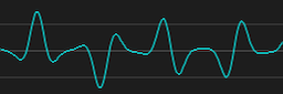 |
|
UNIPOLAR | 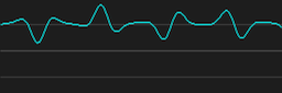 |
|
BIPOLAR | |
AUX OUT
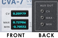
- 3 CVs sockets whose output match exactly the content of CV, MIN and MAX on the front of the device
- Unlike CV OUT, the value of these sockets depend on the state of the , ZOOM, and SCALE controls
- Coupled with automation, these sockets (CV in particular), allow for some interesting and creative results. In this short clip,AUX OUT on the top device is connected to CV IN on the bottom one.
A few words about CV
As stated in the Reason operation manual, "CV signals are typically used to modulate parameter values and do not carry audio". Internally, a CV signal is represented by a floating point number which can range between -10000.0 and +10000.0. In practice, the vast majority of devices use the range between -1.0 and +1.0.
2 critical concepts to understand
- When a device receives a CV value (a floating point number between -10000.0 and +10000.0) it needs to interpret it to give it meaning
- The somewhat familiar representation of CV as an integer number between -127 and +127 is an interpretation of the [-1.0, +1.0] range: everything outside this range is simply clamped at the extreme values
How does CVA-7 interpret CV?
For numeric display (CV, MIN and MAX):
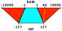
- In RAW mode, there is no interpretation: the value is displayed as it is received (with a precision of 6 digits total), shows the full range ([-10000.0, +10000.0]) and as a result is the only accurate version of the signal
- In % (percent) mode, the signal is first truncated to the [-1.0, +1.0] range, then scaled to an integer value in the [-100, +100] range
- In INT (integer) mode, the signal is first truncated to the [-1.0, +1.0] range, then scaled to an integer value in the [-127, +127] range. This is the default mode, which corresponds to the most common CV use.
Confused?
For keyboard display (including NOTE and GATE):
- For the NOTE representation, the signal is truncated to the [0.0, +1.0] range and is interpreted as a midi note using a standard formula as defined by Reason Studios. As a result, it is expected that every device should interpret a note signal in the same fashion, hence resulting in the same pitch!
- For the GATE representation, the signal is truncated to the [0.0, +1.0] range and scaled to an integer value in the [0, +127] range.
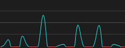
For graph display:
- When the SCALE knob is all the way to the right (default) the signal is converted to a pixel in the range [-1.0, +1.0] and if it exceeds the range it is represented as a red clipping line.
- Turning the SCALE knob adjusts the clipping range thus effectively allowing to show the full signal and get rid of the clipping lines
Automation & Mapping
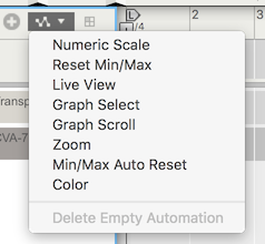
- Most parameters can be automated like any other control in Reason. In order to automate the red selection dot (Graph Select) or the scrollbar (Graph Scroll), you will need to add a track for the device and select the corresponding option in the automation menu as shown in the above screenshot
- Most parameters can be remotely controlled like any other control in Reason. In order to remote map the red selection dot (Graph Select) or the scrollbar (Graph Scroll), you will need to use the top menu "Options/Remote Override Edit Mode" and select the appropriate arrow in the LCD screen
Tips & Tricks
Pausing several CVA-7 devices at the same time
It is quite common to analyze a CV signal both before and after it goes through some device (for instance, to check whether the device transform the signal the way you expect it to). The usual setup is to add a CVA-7 before the device, and another after the device.
In this case, it is most convenient to pause both instances of CVA-7 at the exact same time, to check one single value for example. Here is how you could do it:
- Make sure all concerned devices are inside a Combinator
- Open the Combinator's programmer, and for each CVA-7 instance, set one button to (you must choose the same Combinator's button for each CVA-7, for instance, if you choose to use Button 1, click on the first CVA-7 in the Programmer and set Button 1 to , click on the second CVA-7 and set Button 1 to as well)
Technical details
This section can be skipped and is of interest only if you care about some of the internal details of implementation.Intepretation formulas
- For RAW mode
out = in; - For % mode
temp1 = clamp(in, -1.0, +1.0); temp2 = sign(in) * ceil(((abs(temp1) * 101) - 1) / 2); out = clamp(temp2, -100, +100); - For INT mode
temp1 = clamp(in, -1.0, +1.0); temp2 = sign(in) * ceil(((abs(temp1) * 128) - 1) / 2); out = clamp(temp2, -127, +127); - For NOTE
out = floor(clamp(in * 127 + 0.1, 0, 127)); - For GATE
temp1 = clamp(in, 0, +1.0);
temp2 = sign(in) * ceil(((abs(temp1) * 128) - 1) / 2);
out = clamp(temp2, 0, +127);
CV OUT formulas
- For PASSTHROUGH mode
out = in; - For INVERSE mode
out = -in; - For UNIPOLAR mode
out = (in / 2.0) + 0.5; - For BIPOLAR mode
out = (in * 2.0) - 1.0; // clamped to [-10000, 10000]
Sponsor
pongasoft produces a variety of high-quality and free/open source software. If you would like to support my work and help offset the cost of development tools, web hosting, etc., here is how to do so:
- Tip via Ko-fi
- Send money via PayPal
Thanks
- A big thanks to Clayton Miller for the design and look & feel of the rack extension.
- A big thanks to all the beta testers from the ReasonTalk forum who helped shape the final product. In particular I wanted to call out WongoTheSane, challism and Loque.
News
- The project has been moved to Codeberg.
Old News
1.0.1 - 2021/06/23
- Fixed image sizes to work in Recon and future versions of Reason.
1.0.0 - 2016/11/30
- First release.